Note: I thank Alain Hamblenne for giving me permission to present his photographs here.
When the image on the left is more luminous than the image of right-hand side, the resulting anaglyph inclines toward the red (or toward cyan if darker) and flashes. To compensate for this, it is possible to make a global rebalancing of left/right luminosity .
But, when the variation of light intensity is caused by a detail in the image, this global rebalancing does not work anymore. As an example consider a window that passes external light in a big room. Between the 2 photoshots a cloud passes... Result: the anaglyph flashes on the zone lit by the window, and only there.
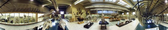
Example:
The external light which enters by the windows of the small room, and that by the ceiling windows, are important. The amount of external light which enters by the windows of the small room, and that by the ceiling windows, less important, and reveal zones previously in the shadow. The color of the image inclines toward red and flashes in the small room, on the wall in front of the camera, on the large skeletons, and the tiles of the large room. It inclines toward cyan in the windows, on the reflections of the tables, and the tiles on the left.
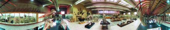
The comparative correction evaluates the luminosity in each point of the image, compares the 2 sights, carries out the correction... and hop, bingo!
All the elements find their colors of origin. There remains a light tan around the large bones on the left, and a light blur on the large bone on the right because of the important shift.
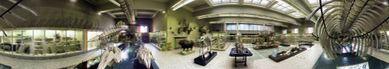
To get good result with this comparative correction, it is necessary to carry out the correction on images that have already been treated as described before.
It is a little bit havy to compute, and lets some defects, but sometimes the only solution to the luninosity problems is to consid them when shooting pictures...
Drawing functions
Click on the box "Pix".
To paint with the brush It is the default mode.
the depth of the cursor, which also corresponds to a shift between the left sight (red) and the right sight (cyan), can be fixed by turning the mousewheel (if present), or by filling in a value in the "Depth" field. The depth of the cursor influences directly the drawing result: a zero value will post the result on the level of the screen, without shift. A positive value will draw behind the screen, and a negative value will draw in front of the screen.
click with the left button of the mouse on the image to draw a point.
click and hold, then draw to create lines.
double-click to load a color from on the image (eyedrop). The value of the color can be taken from its RedGreenBlue composition (RGB value).
To insert text When inserting text, the brush mode is disactivated as long as the text input field contains data.
enter text in the input field.
click on the button "Font", and choose the font type and size.
choose a color (it is the color of the brush, not that which appears in the input field).
move the cursor to the image to choose the place where you want to put the text.
with mousewheel, or via the the depth box, choose if you want to bring the text in front of, behind or onto the screen(zero level).
click (only once) to put the text on the image...
Using image-brushes When using image-brushes, the brush mode is disactivated as long as image-brushes exist.
click on "Load 2d image brush" and choose a file which contains an image, or
click on "Load 3d image brush" and choose a file which contains an image in left sight, then a file which contains the same image in right sight.
move the cursor to the image and choose the place where you want to insert image-brushes.
with the mousewheel, or via an entry in the depth box, choose if you want to bring the text in front of, behind or onto the screen (level zero).
click with the left button of the mouse on the image to drop a brush image.
click and hold, then drag to draw continuous brush images.
it is possible make the background of brushimages transparent allowing insertion of finely cut images, by clicking on "transparent Color". The transparent color is the one held by the brush (white by default) Otherwise, non-transparant color the object will always be painted as a rectangle and with its original background.
When you use the image-brush, it is not possible to change the dimension of image-brush. On the other hand, it is possible to change the dimension of the image you are working with, giving the same result.
Extraction of objects
Click on the tool "Saws"
then click on the image and point by point describe the contour of an object to extract. For that, regulate the depth of the pointer corresponding to that of the object (see above).
the object gradually takes shape in the window "Creation of 3d objects"
in this window, click on "save" and give a name to the left and right images
the option "only Forms" makes it possible to save time by showing only the form and no color.
the object thus created can be reloaded as brushimage
If you want to be able to use the function of transparency to insert the object in another scene, save it in BMP format. (thus avoiding artifacts resulting from JPG compression).
The background of the images thus generated is black. To use the function of transparency of brushimages, you have to enter these values (R=0, V=0, B=0) in the colorbox, because the default color is the white (R=255, V=255, B=255).
It is possible of redifine the dimensions of the extracted left and right images to be able to insert them elsewhere in other proportions.